Motion Control and Obstacle Avoidance of Mobile Robot with Mecanum Wheels
Corresponding email: hassan.m.alwan@uotechnology.edu.iq
Published at : 31 Jan 2025
Volume : IJtech
Vol 16, No 1 (2025)
DOI : https://doi.org/10.14716/ijtech.v16i1.7254
Alwan, HM, Nikolavich, VA, Shbani, A & Vladmirovna, KO 2025, 'Motion control and obstacle avoidance of mobile robot with mecanum wheels', International Journal of Technology, vol. 16, no. 1, pp. 82-96
| Hassan M. Alwan | Mechanical Engineering Department, University of Technology, Alsinaa street, 10066, Baghdad, Iraq |
| Volkov Andrey Nikolavich | High School of Automation and Robotics, Peter the Great St. Petersburg Polytechnic University, 29, Polytekhnicheskaya street, St. Petersburg, 195251, Russia |
| Ali Shbani | High School of Automation and Robotics, Peter the Great St. Petersburg Polytechnic University, 29, Polytekhnicheskaya street, St. Petersburg, 195251, Russia |
| Kochneva Olga Vladmirovna | High School of Automation and Robotics, Peter the Great St. Petersburg Polytechnic University, 29, Polytekhnicheskaya street, St. Petersburg, 195251, Russia |

Most current research on motion control and obstacle avoidance for mobile robot (MR) is primarily focused on static obstacle avoidance, with limited attention to detecting as well as avoiding moving obstacle. As a result, significant research is still needed to address the problems associated with movable obstacle avoidance. The difficulty of movable obstacle avoidance is influenced by several factors related to obstacle, including its size, geometric dimensions, velocity, direction of movement, and acceleration. Other parameters related to the kinematics of MR also play a significant role. Therefore, this research aimed to develop a new method of intelligent detection as well as avoidance of movable and static obstacle. To achieve this purpose, wheeled mobile robot (WMR) was equipped with six ultrasonic sensors to detect the distance between the robot and obstacle. Moreover, a new algorithm was developed based on WMR center position (CP), provided by the control system or distances between the obstacle and WMR detected by sensors. This algorithm determined the position and velocity of movable obstacle. According to the outputs related to movable obstacle, WMR avoided collision by altering its path to follow a feasible alternative path, which was planned based on individual priority. This method was simulated in avoidance of static and movable obstacle using MATLAB Simulink program. The results obtained during the analysis showed that the percentage of maximum additional time to avoid the fixed obstacle was 1.15% while movable obstacle was 0.7% of the total time. In addition, the percentage of maximum additional length to avoid the fixed obstacle was 5.52% while movable obstacle was 3.58% of the total desired length. The results were satisfactory compared to previous research, showing that WMR avoided movable obstacle and returned to the desired path faster than in other investigations.
Obstacle avoidance; Path planning; Robot kinematics Trajectory tracking; WMR
The use of wheeled mobile robot (WMR) is gradually increasing in daily life, industry, and space applications. However, as mobile robot (MR) become more incorporated into various areas of everyday life, challenges are also experienced during the implementation of tasks assigned to the robot, particularly in the aspect of motion control, as well as fixed and movable obstacle avoidance.
Research has devoted significant attention to addressing these challenges over the past decades. These efforts have successfully resolved many problems, especially those related to fixed obstacle. Research on avoiding movable obstacle has not achieved the same level of progress because of its complexity but several significant contributions in this field can be observed. Following the discussion, various findings have implemented several methods for WMR motion control including obstacle avoidance, to ensure smooth task execution along the designated path. (Abed et al., 2024) aimed to review various path planning strategies for MR using different optimization methods obtained from recently published papers in the last five years. In (Al-Mallah et al., 2022) finding, a Type-2 fuzzy logic controller built from human experience was used to guide WMR to reach its predefined destination by controlling linear and angular velocity of the robot, preventing obstacle collision. Moreover, research by (Zghair et al., 2023) focused on finding short and smooth path in a static environment based on hybrid algorithms to avoid collision. In their paper (Abdelwahab et al., 2020) present the Z-number based Fuzzy Logic control for trajectory tracking of differential wheeled mobile robots. The unique point of their approach lies in the ability to encode constraint and reliability in multi-input and multi-output rules. The investigation of (Kuo et al., 2018) allocated a method of obstacle avoidance and focused on curvature constraint for a non–holomonic MR using curvature–constrained streamlines changing via pure pursuit. A new dynamic algorithm was proposed in (Wang et al., 2022) to set the initial direction angle and then improve its evaluation function during implementation of the task to increase the efficiency as well as the flexibility of the algorithm. Rusdinar et al. (2021) developed MR using fuzzy inference system algorithm for its movement with a magnetic line sensor. Following this discussion, the research by (Dang and Bui, 2023) used a binary semantic segmentation (FCN – VGG – 16) to extract features from image captured by monocular camera. This model estimated the position and distance of obstacle in the robot environment. Based on the improved algorithm, the optimized path planning increased the performance of the path of MR. (Feng et al., 2021) paper set out to investigate the usefulness of solving collision avoidance problems with the help of deep reinforcement learning in an unknown environment, especially in compact spaces, such as a narrow corridor. Their research aims to determine whether a deep reinforcement learning-based collision avoidance method is superior to the traditional methods, such as potential field-based methods and dynamic window approach.
Finding by (Wang et al., 2021b) was aimed at developing a review of research progress about local obstacle avoidance method for WMR under complex unknown environment in the last 20 years. A review finding by (Pandey et al., 2017) also focused on the investigation of intelligent navigation methods of WMR that had been developed. This finding included artificial potential field method, grids, Dijikstra algorithm, Voronoi graph, vision sensors, fuzzy logic, neural network, genetic algorithm, and simulated annealing algorithm. The method in (Song et al., 2023) was concerned with the path of MR in a dynamic environment by incorporating the improved ant colony optimization ACO and dynamic window method DWA algorithm. Moreover, an optimization algorithm was used by (Chai et al., 2024) to achieve online tuning of kinematic and dynamic controllers, ensuring fast and accurate convergence of the trajectory tracking error. Work of (Ajeil et al., 2020) deals with the design of intelligent path planning algorithms for a mobile robot in static and dynamic environments based on swarm intelligence optimization. A modification based on the age of the ant is introduced to standard ant colony optimization, called aging-based ant colony optimization (ABACO). Paper (Sun et al., 2020) proposes a robust nonsingular terminal sliding mode (NTSM) control scheme for the path-following problem of an MWOMR. First, a plant model is identified as a second-order state-space equation with four inputs and three outputs to describe the MWOMR’s path-tracking kinematics and dynamics. Afterwards, a multi–input–multi–output NTSM controller is designed for the MWOMR, and the stability of the NTSM control system is verified by means of Lyapunov function. (Yuan et al., 2019) proposed an extended state observer?based sliding mode control (ESO?SMC) strategy for trajectory tracking of a four mecanum wheeled mobile platform (FMWMP) with unknown disturbances and model uncertainties (UDMU) considered. Especially, the extended state observer (ESO) is designed to estimate not only the UDMU but also the unmeasured velocities of FMWMP. Based on the designed ESO, a sliding mode control (SMC) scheme is utilised to ensure the tracking performance as expected. The target of (Tuan et al., 2024) research is to develop a control method for mobile robots operating in dynamic and unknown environments with both static and moving obstacles. The method utilizes a fuzzy logic approach based on a Lidar sensor to gather information about the environment and make decisions for navigation. Approach (Sun et al., 2023) proposes a trajectory-planning scheme and a trajectory-tracking control strategy for a Mecanum-wheeled omnidirectional mobile robot by using artificial potential field and discrete integral terminal sliding mode, respectively. According to the positions of the robot, target, and obstacles, a reference an obstacle-avoidance trajectory is planned and updated iteratively by utilizing artificial potential field functions. Afterward, a discrete integral terminal sliding mode control algorithm is designed for the omnidirectional mobile robot such that the robot can track the planned trajectory accurately (Husain et al., 2024) proposed and designed a strong control scheme for vehicle steer by wire using an integral sliding mode control based on barrier function. This control scheme improved the strength of the controllers better than that of conventional SMC or integral SMC. For the problem of mobile robot’s path planning under the known environment, a path planning method of mixed artificial potential field (APF) and ant colony optimization (ACO) based on grid map has been proposed by (Chen and Liu 2019). (Bernardo et al., 2023) implemented hierarchical control structure using behavior tree (BT) to improve the flexibility and adaptability of an omni-directional MR. This method improved point stabilization and guided the robot to any configuration in the workspace while satisfying state constraints (obstacle avoidance) as well as input constraints (motor limits). A novel adaptive fuzzy prescribed performance control strategy is proposed in (Ding et al., 2024) to deal with the problem of fast accurate trajectory tracking. Instead of the approach angle or the azimuth angle, a pair of heading- and orientation-related auxiliary variables is adopted to deal with the underactuation of the WMR. In place of the transverse function, the barrier function is combined with the adaptive fuzzy logic system to cope with the unknown WMR dynamics.
(Tilahun et al., 2023) proposed trajectory tracking control system using a dual-loop method. In this method, inner loop controlled the dynamics through Adaptive Fuzzy Sliding Mode Control (AFSMC), while outer loop handled kinematics using Adaptive Neuro-Fuzzy Inference System (ANFIS). Generally, the result showed that AFSMC with ANFIS was superior in trajectory tracking for the examined system compared to other controllers. (Yan et al., 2024) designed a local tracking controller that ensured the linear velocity input remained positive, and confirmed the position tracking error was convergent to zero. (Azar et al., 2023) comprehensively examined and analyzed a proposed sliding mode higher–order extended state observer (SMHOESO) convergence using Lyapunov method. According to this analysis, SMHOESO was asymptotically stable, and estimation error was significantly reduced under real-world conditions. The method proposed by (Abukhalil et al., 2020) used pattern recognition of two laser pointers in the view of a single camera to detect objects around the robot. Additionally, distance and angle to the objects were measured using Lagrange interpolation formula applied separately to each laser projection in the framed image. By reviewing the methods used in previous research on movable obstacle avoidance, including those discussed here, this topic still presents many challenges that require further investigation. There is a significant research gap in the field of movable obstacle avoidance, providing more opportunities for further exploration and experiments in this area. Therefore, this research is considered a step in the direction of innovation in the field.
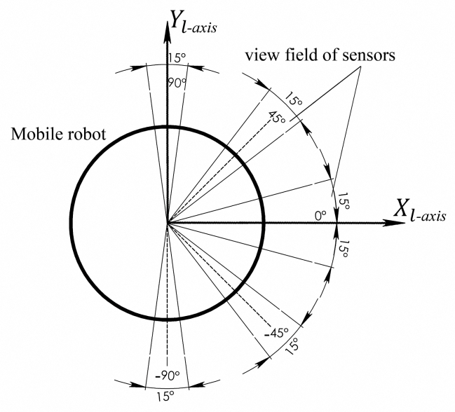
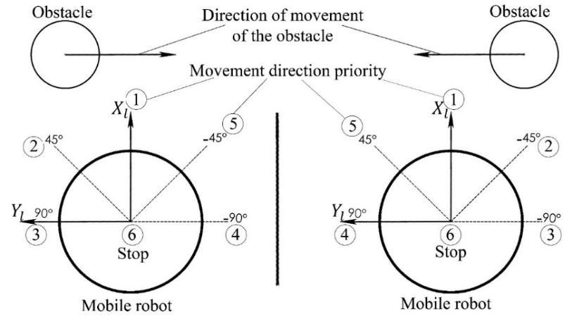
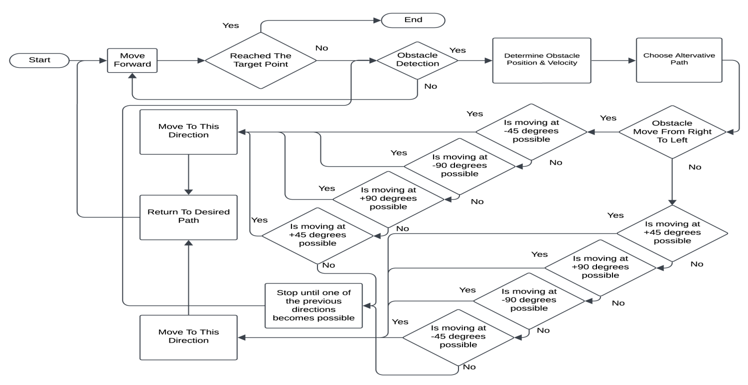
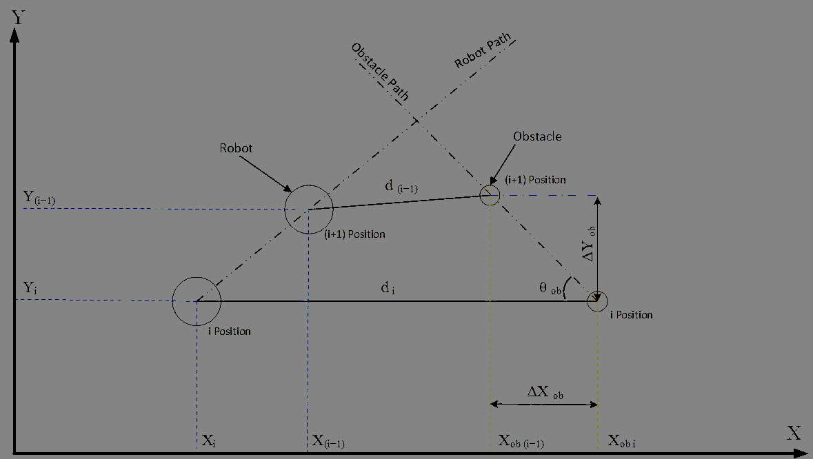
Mobile Robot Kinematic and Dynamic Modeling In this section, kinematic and dynamic model of WMR were obtained. The movement of the proposed WMR (Figure 1) was only in X0Y0 plane. Following the discussion, two different coordinate frames were evident during the research. The first was local coordinate frame (OXY) of the robot where X-axis represented direction of forward movement and Y-axis signified lateral movement as shown in Figure 1. This frame was dynamic and changed as the robot moved, which was related to the second or global coordinate frame (oX0Y0). The velocity of WMR in its local coordinate frame consisted of linear velocity in X and Y direction and a rotation around the center. This velocity was written as, Vr=X Y T . Figure 1 WMR configuration. Due to the rotation between WMR local and global coordinate frame with a rotation angle ? and rotation matrixLGR, velocity Vr was transferred to global coordinate frame as Vrg=Xo Yo T. In addition, the transformation of the velocity was written as Equation 1 (Alwan et al., 2024). Vrg=LGR Vr (1) MR velocity expressed in local coordinates systemVr=Vrx Vry T was used to develop kinematic and dynamic mathematical model concerning angular velocity as well as torques of the wheels. The velocity acting on each helm of the mobile wheels consisted of four components including linear velocity ( X, Y) due to WMR movement. Other components included tangential velocity (? r) caused by angular velocity of the wheel, roller tangential velocity (? r) from angular velocity of the roller which was perpendicular to roller axis (45?) with the robot X-axis. Finally, linear velocity was caused by the rotation of WMR around its center point. WMR inverse kinematic model was obtained by summing up this velocity and was written as Equation 2(Alwan et al., 2024): =JVr (2) Where J was the inverse Jacobian matrix; J=1rwi 1 -1 -(a+b) 1 1 1 1 1 -1 (a+b) -(a+b) (a+b) , and represented the wheel angular velocity matrix ?=1 2 3 4 T. The forward kinematics equation in the robot local coordinates system was written as Equation 3 (Alwan, 2020a), Vr= J+ (3) The forward kinematics equation for WMR in global coordinate system was expressed in Equation 4. Vrg=LGR J+ (4) Dynamic modeling of WMR was obtained using Lagrange formulation. Significantly, the velocity of mass center of WMR in the robot local coordinate system was evaluated according to the theory of (Alwan, 2020b) as written in Equation 5. vC=cos? sin? -sin? cos? Xo Yo (5) WMR moved in a horizontal plane and not in z-axis direction, leading to no potential energy. Kinetic energy of the robot mechanism was caused by linear and rotational velocity of MR as well as four Mecanum wheelsvc, , r?, ?. Moreover, kinetic energy equation was obtained as follows (Equation 6) (Alwan, 2020b). T=12mpvCTvC+Ip2+4[mwr?2+Iw2] (6) Where mp, mw, Ip and Iw were the robot platform mass, wheel mass, robot platform moment of inertia around its mass center, and wheel moment of inertia, respectively. The dynamic of WMR presented the derivation of Lagrange equation, which was written as Equation 7. ddt?Tqi- ?Tqi= Fi i=1,2,3,4 (7) Where qi , qi represented the inputs or angular displacement and angular velocity of i wheel. WMR general form dynamic equation was expressed as Equation 8 (Hasan and Alwan, 2021). Mqq+ Cq,qq+BT S f=1r BT ? (8) Where q= Xo Y0 T, q=Xo Y0 T ,M was the mass and inertia matrix, C signified matrix of coriolis as well as centripetal effect, and B was the input transformation matrix. The elements of each matrix were represented as Equations 9, 10, and 11 (Alwan et al., 2024). C=0 0 mrh1cos?+h2 sin? 0 0 mrh1sin?+h2 cos? 0 0 0 (9) B=(cos?+sin?) (sin?-cos?) -(a+b) (cos?-sin?) (sin?+cos?) (a+b) (cos?-sin?) (cos?+sin?) (sin?+cos?) (sin?-cos?) -(a+b) (a+b) (10) S=sgn(1) 0 0 0 0 sgn(2) 0 0 0 0 0 0 sgn(3) 0 0 sgn(4) (11) Motion Control Design for Trajectory Tracking Backstepping method was adopted to execute the controller during the analysis. The state vector of the generalized coordinate was written as follows (Equation 12). q=qaT qaT T=(Xo Yo o Xo Yo o ) T (12) Based on backstepping controller qawas a subsystem which was equal to virtual input (u1). Trajectory tracking error equation of WMR movement represented the error between desired and actual trajectories as written in Equation 13. e1=qd-qac=ex ey e T=X0d-X0ac Y0d-Y0ac d-ac (13) Where qd=[X0d Y0d d] T was desired robot trajectory and qac=[X0ac Y0ac ac] T represented actual robot trajectory. The derivative of trajectory tracking error equation (13) led to Equation 14. e1=qa-qd=u1-qd (14) For WMR stability testing, Lyapunov expression was considered as Equation 15: V1=12e1T k1 e1 (15) Where was symmetrical and positive. During this analysis, Equation 15 was differentiated concerning time as 16. V1=12e1T k1 e1+12e1T k1 e1=12e1T k1 e1=12e1T k1 u1-qd (16) For stable system, Equation 17 was expressed as, u1=qd-e1 (17) Equation 18 was written as, V1=-12e1T k1 e1?0 (18) Equation 18 showed that the system was asymptotically stable. Obstacle Avoidance Process MR obstacle avoidance decisions were typically based on real-time data concerning the position and velocity of obstacle. This critical information was obtained through sensors during the detection process. In this research, six HC-SR04 ultrasonic sound sensors were used to detect obstacle position and velocity. Two sensors were placed in the front direction of the robot, while the remaining ones were positioned at angles of +45?, +90?, -45?, and -90?. The sensors which were placed in the front direction determined how the obstacle moved. Figure 2 showed the locations of the devices on the robot body and field of view. Moreover, the field of view of these sensors was 15?, and the sensing range was from 2 cm to 400 cm. The obstacle avoidance system of the robot focused on detecting and evading obstructions in a circle less than 0.5 meters radius around the robot center point. In this research, the obstacle avoidance algorithm showed that all obstacle were circular in shape and moved at a constant velocity perpendicular to the path of the robot. Figure 2 The field of view and sensors locations of the robot. The Major points in the obstacle avoidance algorithm were as follows: The robot often moved forward following the desired path since there were no obstacles. When an obstacle was detected on front side of the robot, position, and velocity of the obstruction were determined using the sensors located in that area. The optimal alternative path in which the robot moved was determined based on the direction of how obstacle moved and the signals received from other sensors to identify obstacle-free path. The robot avoided obstacle by changing its original desired path to feasible alternative route, which was possible due to the use of Mecanum wheels. The feasible alternative paths of the robot were arranged according to proposed priority. For example, when the detected obstacle was coming from right to left, the first priority of the robot was to continue its movement until the obstacle passed. Once collision was unavoidable, the robot followed the second priority, which was changing its desired route to feasible alternative path at direction of an angle of -45?. However, when collision could not be avoided, the robot followed the third priority, which was changing its desired path to an alternative route at direction of an angle of -90?. The robot sequentially moved to its fourth and fifth priority and then stopped completely at the final designated position, waiting for obstacle to pass. The feasible alternative path directions in which the robot moved to avoid collision were arranged in the following directions including +45?, +90?, -45?, and -90?. When none of these paths were suitable, the robot stopped moving. Table 1 showed the priority of the feasible alternative path directions. Figure 3 also showed the alternative WMR direction priority in different cases of obstacle avoidance. After avoiding obstacle, the robot returned to tracking the desired path. Obstacle avoidance algorithm methodology was shown in Figure 4 Table 1 Alternative robot paths directions priority in obstacle avoidance process. Figure 3 The alternative WMR directions priority in different cases of obstacle avoidance. Figure 4 The obstacle avoidance algorithm methodology For detecting a movable obstacle and determining its velocity as well as direction, WMR needed to sense the obstruction at two different positions in a known time interval (Figure 5). At each point obstacle center position (CP) in global coordinate frame was determined based on WMR CP and the distance between obstacle and the robot measured by the sensor. When the obstacle positions at the two points were known, the period required to move the obstruction from the first to second point, its velocity and direction, was evaluated as Equation 19. Vob= 2[xob(i+1)-xob(i)2+yob(i+1)-yob(i)]2?t (19) ob=artan?yob?xob The distance between MR and obstacle was more than 500 mm to avoid collision. Relating to the process, this distance was obtained as follows (Equation 20). d=X0t-Xob(t)2+Y0t-Yob(t)2 (20) Figure 5 Detection of movable obstacle

Motion Control and Simulation Results
The aim of the control method was finding an optimal trajectory for MR considering the three main criteria, including short trajectory, smooth trajectory and obstacle–free path, respectively. Moreover, the cost functions used to represent short trajectory f1 as well as its smoothness f2cost functions was written as Equations 21 and 22 (Hasan and Alwan, 2022).
f1X0, Y0=i=1N-1X0t+1-X0(t)2+Y0t+1-Y0(t)2 (21)
f2X0, Y0=i=1N-1arctan Yt+1-Y(t)X0t+1-X0(t) (22)
During the analysis, Artificial Bee Colony (ABC) optimization algorithm was adopted. By initializing the parameters as well as proposing a random number of populations (SN), the process was repeated to reach the maximum cycle number, and the solution was written as Equation 23 (Hasan and Alwan, 2022).
xij=xminj+ rand [0,1]xmaxj-xmin (23)
Where ?= 1,2..SN, j= 1,2..D, D, represented the number of the optimized parameters, rand (0,1) is a real number in interval [0,1], xmax represented upper bounds of xij, and xmin was lower bounds of xij. Following this discussion, a new solution was evaluated as Equation 24 (Hasan and Alwan, 2022):
vi=xij+ ijxij-xik (24)
Where k ? [1, 2…SN]. When the nectar amount of (vij) was better than (xij), (xij) was changed by (vij) and (vij) became the new population number.
The controller algorithm generated suitable improvements to control MR wheel angular velocity and the robot movement along original or alternative trajectories. During the algorithm testing, simulations were performed to show the motion of the robot along a question-sign-shaped trajectory. Moreover, simulation results of equation (17) were performed in MATLAB Simulink program. The following geometric dimensions were adopted to perform numerical simulation movement of the robot including Mecanum wheel angle ? = ?/4[rad], WMR represented as a cylinder of R = 0.25[m] and the obstacle was as a colander of a radius Rob = 0.15[m]. Figure 6 showed WMR control architecture diagram used to simulate the results of motion control and obstacle avoidance.
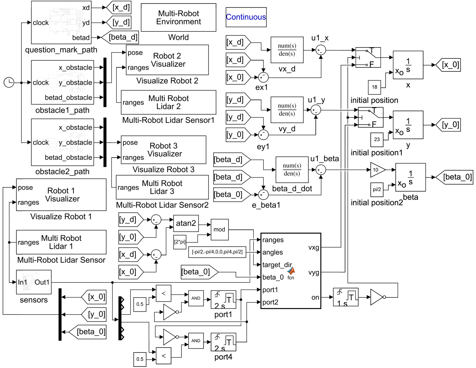
Figure 6 Control architecture diagram.
Simulation and validation of two examples of obstacle avoidance were presented in this section.
Example–1: Avoidance of movable obstacle was implemented in this example, where WMR operated in unknown environment containing two movable obstacle, and each of the obstacle intersected the desired path in two points. When one or more of the sensors detected an obstacle, signal was sent to the controller to determine the position of obstacle center. After a period, this procedure was repeated to determine the position of the center. Based on the two records, obstacle velocity and angle of its direction were determined. When the distance between WMR and obstacle was detected to be less than 500 mm, MATLAB initiated avoidance algorithm. This algorithm sent the information to the controller, adjusting MR wheels angular velocity and enabling it to follow an alternative path. The selected path was determined based on the obstacle velocity, movement direction, and priority of feasible alternative paths. Results of this analysis showed that the path length travelled by WMR without obstacle was 1026.7 cm in 37.17 seconds, while length travelled with movable obstacle was 1162.5 cm in 38 seconds, respectively. Table 2 showed the added path length and time as a result of avoiding each of the four obstacle. Additionally, trajectory tracing error between WMR desired and its actual path to avoid the collision was shown in Figure 7. Simulated result of movable obstacle avoidance process which included WMR desired and actual path to avoid the collision, as well as movable obstacle paths was shown in Figure 8. The results of this analysis showed that the percentage of maximum additional time to avoid movable obstacle was 0.7% of the total time. In addition, the percentage of maximum additional length to avoid this obstacle was 3.58% of the total desired length.
Table 2 Path length and time increase from movable obstacle avoidance.
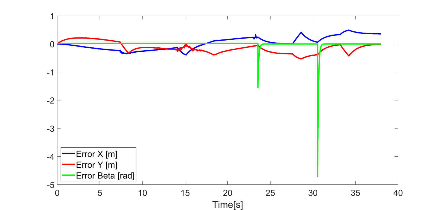
Figure 7 Trajectory tracking error and avoidance of movable obstacle
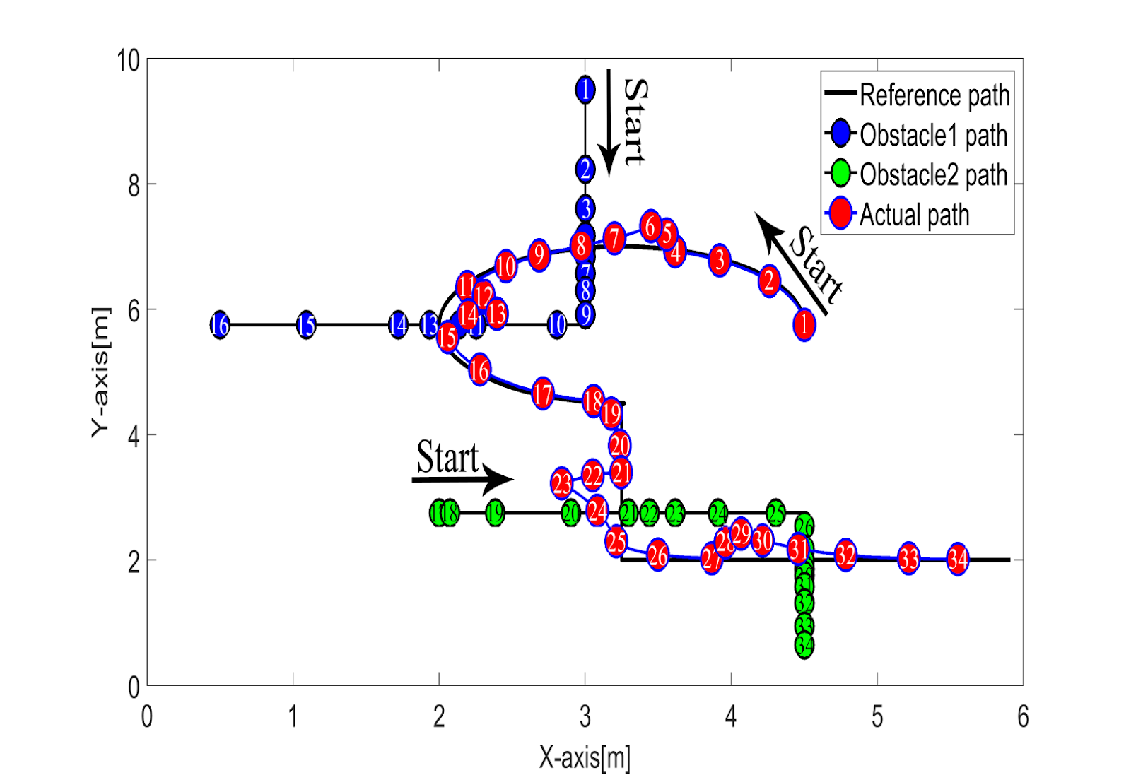
Figure 8 Simulated results of movable obstacle avoidance trajectory
Example–2: This example was allocated to static obstacle avoidance during the analysis. WMR worked in an unknown environment containing four static obstacle, located in various positions. When one or more of the sensors detected an obstacle, signal was sent to the controller in determining the position of obstacle center. Moreover, when the detected distance between WMR and obstacle was less than 500 mm, MATLAB initiated the avoidance algorithm and sent information to the controller, adjusting MR wheels angular velocity to follow an alternative path based on obstacle position and priority of feasible alternative paths. The results of this process showed that path length travelled by WMR without obstacle was 1098cm in 38.88 seconds, while with static obstacle was 1244.5 cm in 40 seconds, respectively. Table 3 showed the added path length and time as a result of avoiding each of the four obstacles. Trajectory tracing error between WMR desired and its actual path to avoid the collision was shown in Figure 9. Additionally, simulated result of static obstacle avoidance process which included WMR desired and actual WMR path to avoid the collision, as well as fixed obstacle poisons was shown in Figure (10). Results of the analysis showed that the percentage of maximum additional time to avoid fixed obstacle was 1.15% of the total time. In addition, the percentage of maximum additional length to avoid this obstacle was 5.52% of the total desired length. In comparison with previous research under the same conditions, this investigation found that in (Hasan and Alwan, 2022) and (Hasana and Alwan, 2021), MR traveled a path of 516.15cm in 25.989 seconds, and 1451.06cm in 73.5 seconds, respectively. Meanwhile, MR traveled 1098cm in 38.88 seconds in this research, signifying that WMR avoided the obstacle faster than in other methods.
Table 3 Path length and time increase from static obstacle avoidance.
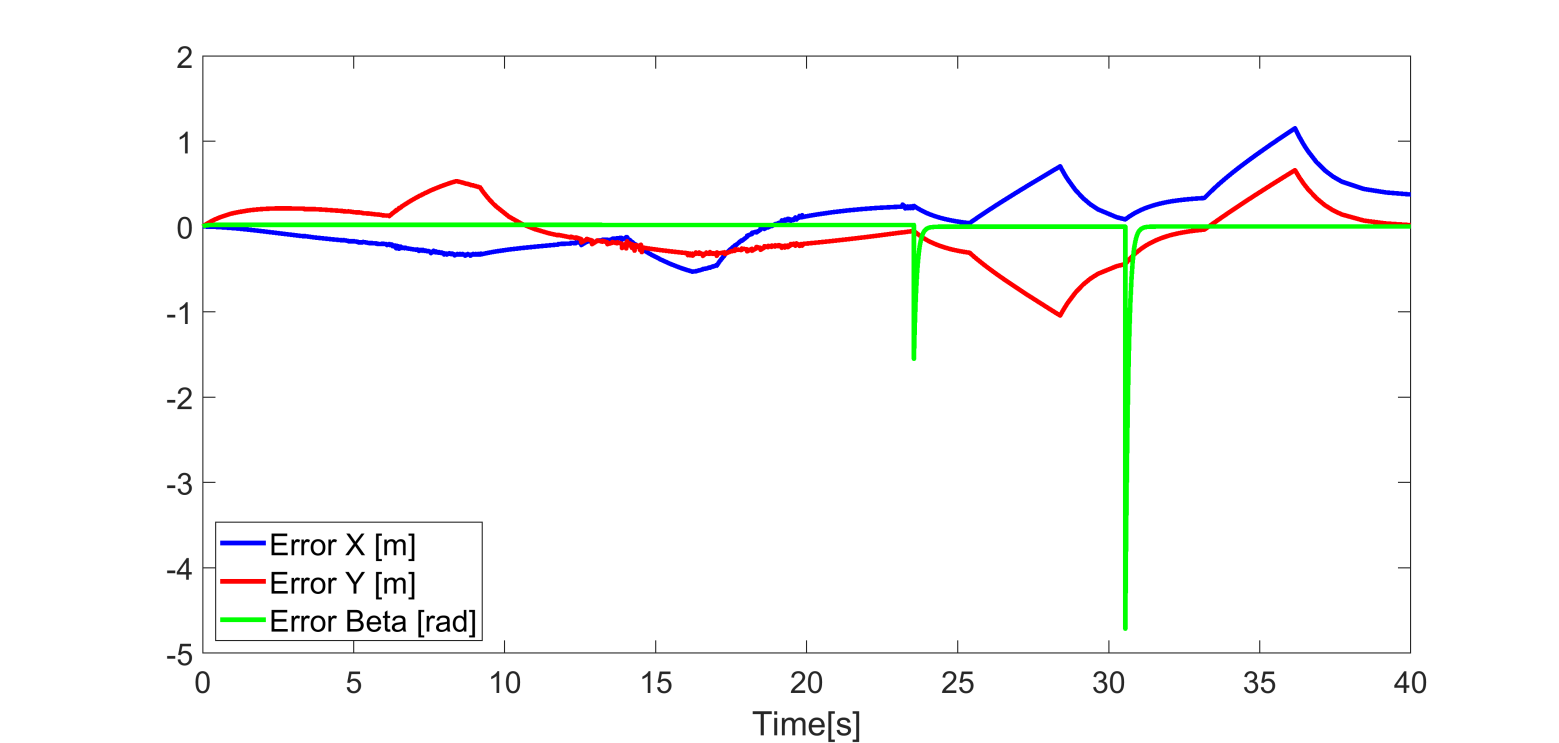
Figure 9 Trajectory tracking error while avoidance of static obstacle.
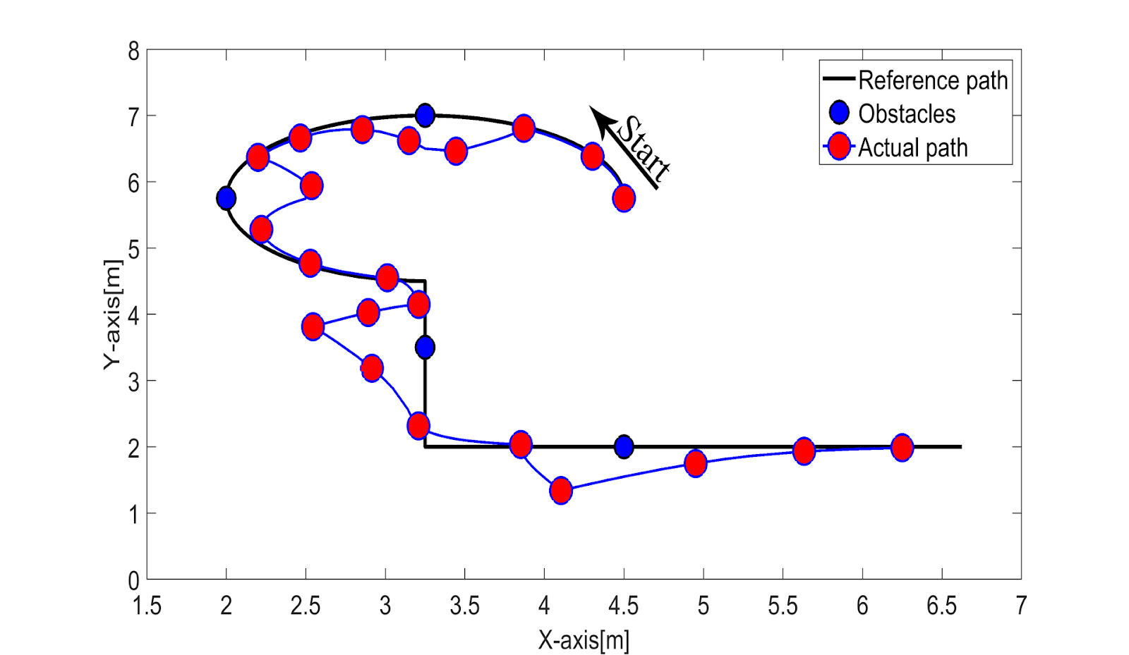
Figure 10 Simulated results of static obstacle avoidance trajectory.
The analysis signified that the tracking error in the previous two examples increased when avoiding obstacle. This process was normal, but a relatively large error occurred when crossing 90? angles in the track. The error was the result of basic error represented by displacement from the intended aimed point, which was approximately 0.36m, and the fault was rectified at the end of track. Following the discussion, displacement occurred because the aimed point kept changing at every moment, but response movement of the robot was slower than the speed of change, leading to displacement.
In conclusion, this research developed MR equipped with four Mecanum wheels and formulated its kinematic as well as dynamic models. Trajectory tracking control system was also designed using obstacle avoidance algorithm for both stationary and movable obstacle. The performance of the robot was thoroughly evaluated, and results showed that the machine successfully achieved its main objectives of avoiding all encountered stationary or movable obstacle. Additionally, the outcome showed that the avoidance of the four static obstacle increased path length by 13% and 2.87% for the time to reach target. As for the four movable obstacle, path length increased by 11% and 2.15% for the time to reach target. Trajectory tracking error during the analysis was significant only during obstacle avoidance maneuvers, showing the effectiveness of the control system in normal conditions. However, a lateral displacement error of 0.36 meters was observed, attributed to slow response of the robot to dynamically changing target points. The error occurred only at inflection points because the running of obstacle avoidance algorithm slowed down the response at these points. This outcome signified that, although the control and avoidance algorithms were strong, further optimization would be needed to improve responsiveness of the robot to rapidly changing target points. Future research should focus on improving the responsiveness and accuracy of trajectory tracking system to mitigate lateral displacement errors. The investigations should also focus on achieving more precise navigation and testing the improved methods with MR as well a movable obstacle under more complex conditions.
The authors are grateful to everyone who provided support from University of Technology as well as High School of Automation and Robotics at Peter the Great Saint Petersburg Polytechnic University.
Nomenclature
WMR Wheeled Mobile Robot
FMWMR Four Mecanum Wheeled Mobile Robot
LQR Linear Quadratic Regulator
ACO Ant Colony Optimization
DWA Dynamic Window Approach
ABC Artificial Bee Colony
PID Proportional Integral Derivative
ESO Extended State Observer
SMHOESO Sliding Mode Higher – Order Extended State Observer
SMC Sliding Mode Control
MPC Model Predictive Control
Author Contributions
Hassan M. Alwan; Conceptualization, Methodology, Derivation of Robot Kinematic and Dynamic Models and Formal Analysis, Volkov A.N.; Review and Supervision, Ali Shbani and Kochneva O.V.; Results Simulation, Software and Project Administration. All authors have read and agreed to the published version of the manuscript.
Conflict of Interest
The authors confirm that there is no conflict of interest to declare for this publication
Abdelwahab, M, Parque, V, Elbab, AMF, Abouelsoud, A & Sugano, S 2020, ‘Trajectory tracking of wheeled mobile robots using z-number based fuzzy logic’, IEEE Access, vol. 8, pp. 18426-18441, https://doi.org/10.1109/ACCESS.2020.2968421
Abed, MS, Lutfy, OF & Al-Doori, QF 2021, ‘A review on path planning algorithms for mobile robots’, Engineering and Technology Journal, vol. 39, no. 5, pp. 804-820, https://doi.org/10.30684/etj.v39i5A.1941
Abukhalil, T, Alksasbeh, M, Alqaralleh, B & Abukaraki, A 2020, ‘Robot navigation system using laser and monocular camera’, Journal of Theoretical and Applied Information Technology, vol. 98, pp. 714-724
Ajeil, FH, Ibraheem, IK & Azar, AT 2020, ‘Grid-based mobile robot path planning using aging-based ant colony optimization algorithm in static and dynamic environments’, Sensors, vol. 20, no. 7, article 1880, https://doi.org/10.3390/s20071880
Al-Mallah, M, Ali, M & Al-Khawaldeh, M 2022, ‘Obstacle avoidance for mobile robot using type-2 fuzzy logic controller’, Robotics, vol. 11, no. 6, article 130, https://doi.org/10.3390/robotics11060130
Alwan, HM 2020a, ‘Dynamic analysis modeling of a holonomic wheeled mobile robot with mecanum wheels using virtual work method’, Journal of Mechanical Engineering Research and Developments, vol. 43, no. 6, pp. 373-380
Alwan, HM 2020b, ‘Path tracking simulation of a wheeled mobile robot with three mecanum wheels’, International Review of Mechanical Engineering, vol.14, no. 8, pp. 516-522, https://doi.org/10.15866/ireme.v14i8.19647
Alwan, HM, Nikolaevic, VA, Hasan, SF & Vladmerovna, KO 2024, ‘Kinematic and dynamic modeling based on trajectory tracking control of mobile robot with mecanum wheels’, International Journal of Technology, vol. 15, no. 5, pp. 1473-1486, https://doi.org/10.14716/ijtech.v15i5.6908
Azar, AT, Abed, AM, Abdul-Majeed, FA, Hameed, IA, Jawad, AJM, Abdul-Adheem, WR, Ibraheem, IK & Kamal, NA 2023, ‘Design and stability analysis of sliding mode controller for non-holonomic differential drive mobile robots’, Machines, vol. 11, no. 4, article 470, https://doi.org/10.3390/machines11040470
Bernardo, R, Sousa, JMC, Botto, MA & Goncalves, PJS 2023, ‘A novel control architecture based on behavior trees for an omni-directional mobile robot’, Robotics, vol. 12, no. 6, article 170, https://doi.org/10.3390/robotics12060170
Chai, B, Zhang, K, Tan, M & Wang, J 2024, ‘An optimal robust trajectory tracking control strategy for the wheeled mobile robot’, International Journal of Control, Automation and Systems, vol. 22, pp. 1050-1065, http://dx.doi.org/10.1007/s12555-022-0902-1
Chen, G & Liu, J 2019, ‘Mobile robot path planning using ant colony algorithm and improved potential field method’, Computational Intelligence and Neuroscience Journal, vol. 2019, article 1932812, https://doi.org/10.1155/2019/1932812
Dang, TV & Bui, NT 2023, ‘Multi-scale fully convolution network-based semantic segmentation for mobile robot navigation’, Electronics, vol. 12, no. 3, article 533, https://doi.org/10.3390/electronics12030533
Dang, T-V & Bui, N-T 2023, ‘Obstacle avoidance strategy for mobile robot based on monocular camera’, Electronics Journal, vol. 12, no. 8, article 1932, https://doi.org/10.3390/electronics12081932
Ding, W, Zhang, JX & Shi, P 2024, ‘Adaptive fuzzy control of wheeled mobile robots with prescribed trajectory tracking performance’, IEEE Transactions on Fuzzy Systems, vol. 32, no. 8, https://doi.org/10.1109/TFUZZ.2024.3401691
Feng, S, Sebastian, B & Ben-Tzvi, P 2021, ‘A collision avoidance method based on deep reinforcement learning’, Robotics, vol. 10, no. 2, article 73, https://doi.org/10.3390/robotics10020073
Hasan, SF & Alwan, HM 2022, ‘Local path planning of a four mecanum wheeled mobile robot based on new modified ultrasonic sensors with experimental implementation’, International Journal of Mechanical Engineering, vol. 7, no. 1, pp. 4621-4627
Hasan, SF& Alwan, HM 2021, ‘Obstacle avoidance of wheeled mobile robot by using modified artificial bee colony optimization’, Design Engineering, vol. 7, pp. 3713-3727
Hasana, SF & Alwan, HM 2021, ‘Modelling and control of wheeled mobile robot with four mecanum wheels’, Engineering and Technology Journal, vol. 39, no. 5, pp. 779-789
Husain, SS, Al-Dujaili, AQ, Jaber, AA, Humaidi, AJ & Al-Azzawi, RS, 2024, ‘Design of a Robust Controller Based on Barrier Function for Vehicle Steer-by-Wire Systems, ‘World Electric Vehicle Journal, 15, 17. https://doi.org/10.3390/wevj15010017
Kuo, P-L, Wang, C-H, Chou, H-J & Liu, JS 2018, ‘A real-time hydrodynamic-based obstacle avoidance system for non-holonomic mobile robots with curvature constraints’, Applied Sciences Journal, vol. 8, no. 11, article 2144, https://doi.org/10.3390/app8112144
Pandey, A, Pandey, S & Parhi Dr 2017, ‘Mobile robot navigation and obstacle avoidance techniques: a review’, International Robotics &Automation Journal, vol. 2, no. 3, pp. 96-105
Rusdinar, A, Purnama, I, Fuadi, AZ, Adiluhung, H, Wicaksono, M, Risnanda & Ningrum, RA 2021, ‘Automated ultraviolet c light mobile robot for room sterilization and disinfection’, International Journal of Technology, vol. 12, no. 4, pp. 854-864, https://doi.org/10.14716/ijtech.v12i4.4817
Song, B, Tang, S & Li, Y 2023, ‘A new planning integrating improved aco and dwa algorithms for mobile robots in dynamic environments’, Mathematical and Biosciences and Engineering Journal, vol. 21, no. 2, pp. 2189-2211, http://dx.doi.org/10.3934/mbe.2024096
Sun, Z, Hu, S, Miao, X, Chen, B, Zheng, J, Man, Z & Wang, T 2023, ‘Obstacle - avoidance trajectory planning and sliding mode-based tracking control of an omnidirectional mobile robot’, Frontiers In Control Engineering, vol. 4, article 1135258, https://doi.org/10.3389/fcteg.2023.1135258
Sun, Z, Xie, H, Zheng, J, Man, Z, & He, D 2020, ‘Path-following control of mecanum-wheels omnidirectional mobile robots using nonsingular terminal sliding mode’, Mechanical Systems and Signal Processing, vol. 2, no. 2, article 107128, https://doi.org/10.1016/j.ymssp.2020.107128
Tilahun, AA, Desta, TW, Salau, AO & Negash, L 2023, ‘Design of an adaptive fuzzy sliding mode control with neuro-fuzzy system for control of a differential drive wheeled mobile robot’, Cogent Engineering, article 2276517, https://doi.org/10.1080/23311916.2023.2276517
Tuan, PM, Tai, ND, Huy TQ & Thinh, NT 2024, ‘Flexible path planning of mobile robot for avoiding the dynamic obstacle using fuzzy controllers’, International Journal of Mechanical Engineering and Robotics Research, vol. 13, no. 1, pp 126-132, doi: 10.18178/ijmerr.13.1.126-132
Wang, H, Ma, X & Zhu, L 2022, ‘Obstacle avoidance path planning of mobile robot based on improved DWA’, Journal of Physics: Conference Series, article 2383, doi:10.1088/1742-6596/2383/1/012098
Wang, W, Zhao, J, Li, Z & Huang, J 2021b, ‘Smooth path planning of mobile robot based on improved ant colony algorithm, Journal of Robotics, vol. 202, https://doi.org/10.1155/2021/4109821
Wang, Y, Li, X, Zhang, J, Li, S, Xu, Z & Zhou, X 2021a, ‘Review of wheeled mobile robot collision avoidance under unknown environment’, Science Progress Journal, vol. 104, no. 3, https://doi.org/10.1177/00368504211037771
Yan, L, Ma, B & Jia, Y 2024, ‘Trajectory tracking control of nonholonomic wheeled mobile robots using only measurements for position and velocity’, Automatica, vol. 159, article 111374, https://doi.org/10.1016/j.automatica.2023.111374
Yuan, Z, Tian, Y, Yin, Y, Wang, S, Liu, J & Wu, L 2019, ‘Trajectory tracking control of a four mecanum wheeled mobile platform: an extended state observer-based sliding mode approach’, The institution of Engineering and Technology, vol. 4, no. 5, pp. 1-12, https://doi.org/10.1049/iet-cta.2018.6127
Zghair, NAK & Al-Araji, AS 2023, ‘Dynamic obstacle avoidance algorithm for autonomous mobile robot’, Iraqi Journal of Computers, Communications, Control and System Engineering, vol.23, no. 2, pp. 63-82