Thermal Performance Analysis of Dry Unit of Hybrid Closed Cooling Tower
Corresponding email: v.v.kharkov@gmail.com
Published at : 31 Jan 2025
Volume : IJtech
Vol 16, No 1 (2025)
DOI : https://doi.org/10.14716/ijtech.v16i1.7081
Madyshev,
I, Kharkov, V, Vakhitov, M & Kuznetsov, M 2025, 'Thermal performance
analysis of dry unit of hybrid closed cooling tower', International Journal of Technology, vol.
16, no. 1, pp. 27-45
| Ilnur Madyshev | Department for Food Production Equipment, Institute of Food Engineering and Biotechnology, Kazan National Research Technological University, Russian Federation, 420015, Kazan, Karl Marx st., 68 |
| Vitaly Kharkov | 1. Department for Food Production Equipment, Institute of Food Engineering and Biotechnology, Kazan National Research Technological University, Russian Federation, 420015, Kazan, Karl Marx st., 68 2. |
| Marsel Vakhitov | Department for Food Production Equipment, Institute of Food Engineering and Biotechnology, Kazan National Research Technological University, Russian Federation, 420015, Kazan, Karl Marx st., 68 |
| Maxim Kuznetsov | 1. Department for Food Production Equipment, Institute of Food Engineering and Biotechnology, Kazan National Research Technological University, Russian Federation, 420015, Kazan, Karl Marx st., 68 2 |

Effective cooling technology is essential for ensuring the sustainable development of industrial enterprises. Therefore, this study aimed to propose a hybrid closed cooling tower (CCT) with a fill unit composed of a finned pipe coil and inclined corrugated plates (ICP). A mathematical model of the hot water cooling process in the proposed cooler, operating in dry mode was developed using the number of heat transfer units (NTU). The model was validated with experimental data across different mass flow rates of process water, cooling air, and initial temperature conditions. The results showed that the finned surface of the coil pipes enhanced the heat flow rate by 2.63–3.22 times, depending on the Reynolds number by air, and improved the efficiency of heat transfer by 2.34 times.
Heat transfer; NTU; Pipe finning; Water cooling
Water recycling systems are crucial in optimizing water resource utilization, forming a cornerstone of sustainable development of modern enterprises (Liang et al., 2024; Whulanza et al., 2024; Sati and Periaswamy, 2024; Berawi., 2014). Among the various coolers used in the systems, cooling towers are the most prevalent (Madyshev et al., 2020; Bahadori, 2016). Cooling towers are categorized into wet and dry types based on the heat transfer mechanism (Nemati et al., 2024). wet cooling towers consume substantial quantities of water (Muthukumar et al., 2019), with a significant portion lost to evaporation, leading to resource wastage (Al-Wakedet and Behnia, 2007). Additionally, the operating cost is high due to the need for regular water quality stabilization (Arefimanesh & Heyhat, 2024; Gao et al., 2016). The dry cooling tower is widely used in water-scarce areas due to the lower operational and maintenance costs, as well as the water conservation ability. However, its thermal performance is considerably lower compared to wet towers (Sun et al., 2017; He et al., 2016).
The most versatile and promising cooling tower for chilling process water is a hybrid-type design (Rahem, 2018). Its operation includes the liquid flowing through the internal heat exchanger and cooling using both air and water supplied from above through a sprayer. Since this is a closed circuit, the loss of liquid is excluded in the primary circuit, ensuring water remains clean, preventing the formation of precipitation, and avoiding corrosion of heat exchange surfaces. At low ambient temperatures, the tower operates only in dry mode, relying on air for cooling. When the ambient temperature rises above 16–18°C, supplementary spraying of the heat exchange surfaces was adopted to maintain effective cooling.
The primary objectives of the study on hybrid cooling towers are to evaluate and improve the thermal performance. Zhao et al. (2023) investigated the cooling performance of the dry-wet hybrid cooling tower with different types of fill packs. By changing the operating conditions, such as ambient humidity, temperature, and fan speed, a performance control strategy was developed. Zaza et al. (2024) examined the heat transfer efficiency of the hybrid systems in terms of fouling deposition on heated surfaces caused by variations in cooling water quality. Using experimental correlations between water quality and foiling resistance, a numerical simulation was conducted to estimate the thermal performance of the system over a year. These results provide insights into effective methods for cleaning fouled pipes. Significant improvements in thermal performance were achieved by incorporating air jet cleaning, which increased the heat transfer of polymer pipe bundles by 6.1% without additional water consumption. Rasheed and Makki (2023) designed a hybrid tower comprising a wet section and a compact air-cooled heat exchanger. Using a modified approach, it was established that high humidity of the air enhances the efficiency of the dry section. Additionally, the increase in humidity ratio was approximately one-seventh of the wet section.
Yu et al. (2023) predicted the thermal performance of the parallel-path hybrid cooling tower. To achieve this, an accurate numerical model was developed by integrating a thermal performance model with an air distribution model. Results showed that the contribution ratio of the number of rows in the dry part to the total air flow rate was 76.75%, while the cooling air flow rate ratio between the dry and wet sections was 61.73%. Vitkovic et al. (2016) experimentally determined the thermal performance of the cooling tower operated in wet, dry, and hybrid modes. The hybrid cooling tower includes 2 circuits, namely a finned pipe bundle and a recirculation line. The efficiency in the hybrid mode was obtained as a function of dry and wet cooling. In conclusion, the lower efficiency of the hybrid cooling tower can be improved by increasing the number of finned pipes.
Sonia et al. (2016) conducted a thermoeconomic survey of hybrid cooling tower systems in thermal power plants, focusing on water consumption. Performance-influencing factors such as ambient temperature and relative humidity, were considered. The results showed that the selection of a cooler should be guided by power production or water consumption, especially in specific regions. Taimoor et al. (2022) performed a techno-economic analysis of a hybrid cooling cycle for high-end cooling loads using ASPEN tools. An integrated cycle consisting of dry air cooling and compression refrigeration was proposed. In conclusion, the cooling cycle with an improved heat transfer coefficient (HTC) provides cost and resource savings. Numerous studies (Hassab, 2023; Reuter and Anderson, 2016; Budihardjo et al., 2015) utilized the number of heat transfer units (NTU) to evaluate the thermal performance of the cooling tower.
Among the key challenges faced by closed cooling towers (CCT) of hybrid type operating in dry mode is reduced thermal performance due to the low values of the HTC. Therefore, investigating the factors that can enhance HTC remains a critical area of study (Susmiati et al., 2022; Ravelo-Mendivelso et al., 2023).
Flow arrangement analysis and pipe coil characteristics, including pipe diameter and surface type, significantly influence the performance of CCT (Hassab, 2023; Reuter and Anderson, 2016; Heyns and Kröger, 2010). The finning of the heat exchanger surfaces increases the heat transfer area and induces turbulent flow, leading to improved device efficiency (Vitkovic, 2016; Howongsakun et al., 2016).
Jiang et al. (2013) investigated the influence of flow arrangement on the performance of a cross-flow CCT. In this study, cooling air and process water operated in counter-flow, while spray water interacted in cross-flow with the other 2 fluids. The numerical results showed that this flow arrangement provides fairly uniform heat and mass transfer forces. Zhou et al. (2018) an experiment and simulation outcomes of the thermal performance analysis of the CCT with different cooling water directions. The results showed that the concurrent flow arrangement of cooling water and spray water compared with the counter case (with the same direction as ambient air) promotes the efficiency of the CCT by up to 9.5%.
Budihardjo et al. (2015) studied the CCT with a counter-flow arrangement of air and process water. The value of NTU was reported to be directly proportional to the air mass flow rate. Hassab et al. (2023) presented a new correlation between effectiveness and NTU to analytically calculate the thermal performance of the cross-flow CCT.
Wei et al. (2017) studied the counter-flow CCT with 2 different arrangements. In the first case, the flows of process and spray waters were parallel, while the airflow was in the opposite direction. In the second case, process water and air moved in the horizontal direction, but spray water flows from the top to the bottom. Despite the different flow arrangements, the thermal performance was determined by the same parameters.
To address the problem of low heat transfer efficiency, a hybrid CCT was proposed, incorporating a fill unit with inclined corrugated plates (ICP) and a finned pipe coil (Figure 1). The significant feature of the developed device is the ability to operate in both dry (closed circuit) and wet modes (with a spray flow). In the dry mode, water flows inside an integrated pipe coil, with the external surface cooled by airflow. This design enhances the process of chilling water in the dry unit by increasing the HTC values and creating a developed heat exchange surface. Additionally, the presence of corrugated plates with holes generates additional flow turbulence, leading to an increase in the efficiency of the coil (Madyshev, and Kharkov, 2024; Madyshev et al., 2022; Kharkov, 2018).
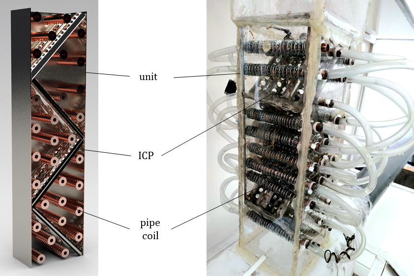
Figure 1 The longitudinal section (a) and the real image (b) of the dry unit of the hybrid CCT (cooler).
The novelty of the proposed cooler lies in the development of an enhanced heat transfer surface within the unit, achieved through the integration of ICP and the external finning of the coil pipes. This design equalizes thermal resistance and intensifies the heat transfer process to be intensified by expanding the area and increasing air flow velocity.
The study aims to develop a mathematical model for analyzing the chilling process of water in the unit of the hybrid CCT operating in dry mode, incorporating both plain and finned coil pipes. The model was designed to evaluate the thermal performance of the unit and validated using experimental data at different mass flow rates of process water and cooling air, as well as the initial temperatures.
2.1. Experimental part
The perforated ICP were located perpendicular to each other, forming a zigzag pattern within the profile of the dry unit in the hybrid cooler. Coil pipes, designated for process water, were mounted across the plates. The operation of the hybrid cooler in dry mode includes water circulating inside the coil pipes, which forms a closed cooling system. In this context, hot water, heated in the process equipment, entered through the pipe installed at the bottom of the unit. The flow sequentially passed through other pipes, moving from the bottom to the top of the unit. The process water was cooled by ambient air, which was introduced at the base of the unit, flowing perpendicular to the coil pipes and along the external surfaces of the heated coils. Furthermore, the warm air after absorbing heat, was released into the ambient environment from the unit top. In this system, the primary resistance to heat transfer arises from the air-side heat exchange process, where HTC values had significant variability, differing by several orders of magnitude.
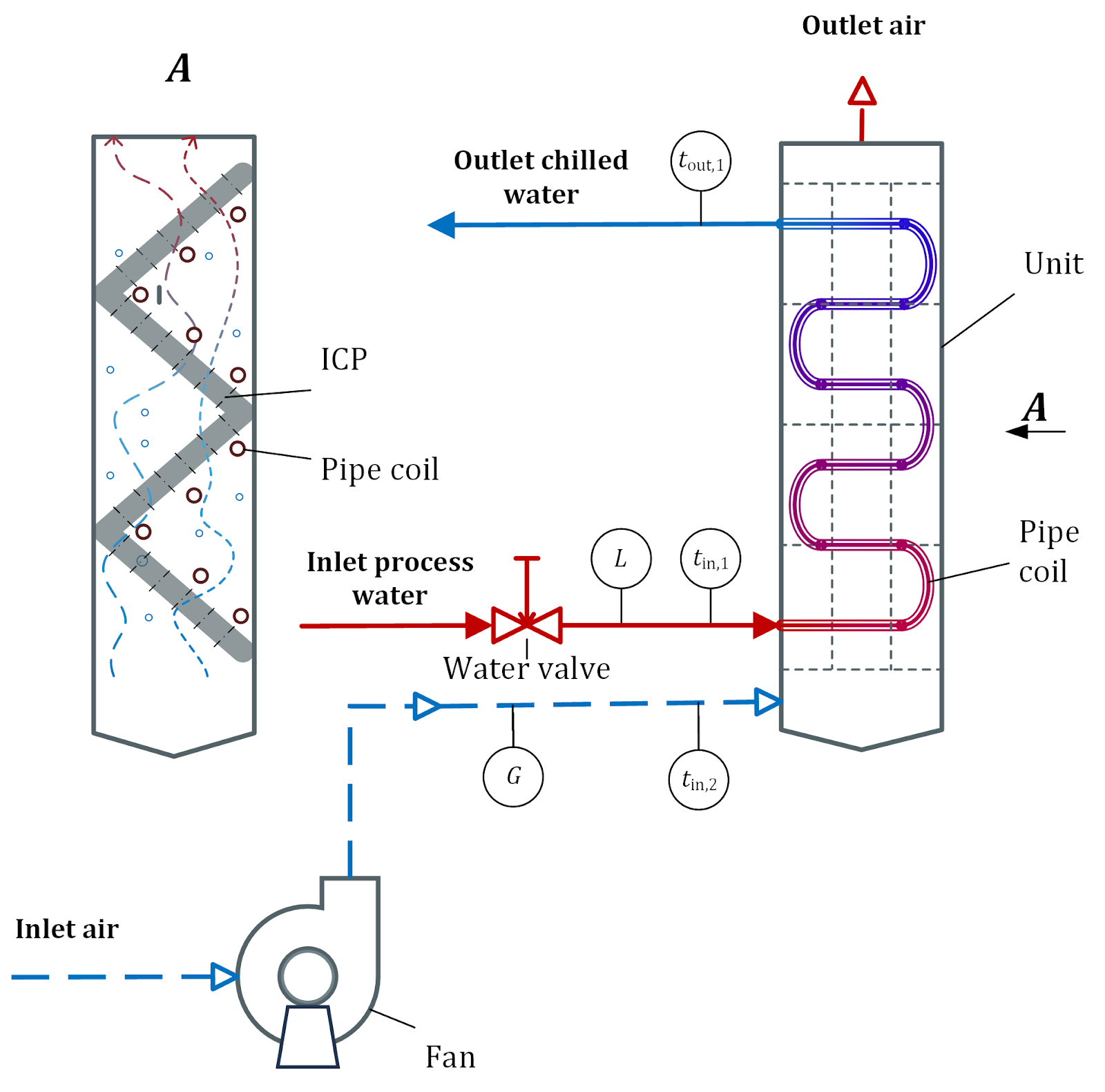
Figure 2 The experimental installation of the dry unit of the hybrid cooler.
Experimental studies were conducted using a water-air system to evaluate the thermal characteristics of process water chilling in the dry unit of the cooler, which featured a square cross-section of 100 mm, as detailed in Figure 1. The unit consists of 4 ICPs with a total height of 340 mm. Each plate had a thickness of 0.6 mm and a curvature radius of 7.5 mm. Holes of different diameters were drilled into the surfaces of the plates to facilitate the passage of cooling air. The pipe coil comprised a circuit of 30 copper pipes, each with a diameter of 8 mm and a length of 125 mm, connected by silicone hoses. Circular finning was applied to each pipe by fixing 19 steel rings with a thickness of 0.5 mm and spaced 5 mm apart. The fin had a height of 3.5 mm, enhancing the heat transfer surface, as presented in Figure 3.
The experiment includes 4 test series, with 2 conducted on the coil with plain-wall pipes and the remaining on finned-wall. Before conducting experiments, the cooler was turned on for 5 minutes to ensure the steady-state conditions of the system. The accuracy of the different sensors is shown in Table 1, while the locations were labeled with circles, as detailed in Figure 2.
During the tests, a constant mass flow rate of water was established in the pipe coil of the dry unit in the hybrid cooler using a valve. The water temperature was set at the inlet to the coil and observed changes did not exceed 0.2–0.4 °C, reflecting an insignificant variation in the parameter over time. When the constant values of the parameters presented in Table 1 were achieved, the rotation speed of the centrifugal fan was changed using the Mitsubishi FR E-700 inverter. As a result, the fan capacity was adjusted as well as the average air velocity in the dry unit of the hybrid cooler. After each change in the rotation speed of the centrifugal fan during a series of tests, a steady state was reached within an average of 5 to 7 minutes. To obtain the accuracy of the measurements, each experimental procedure was repeated 3–5 times.
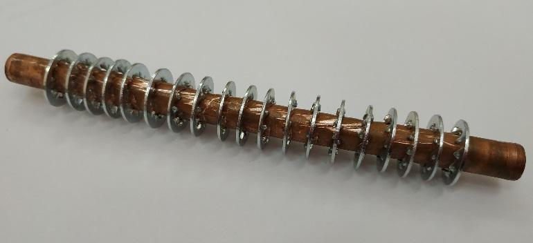
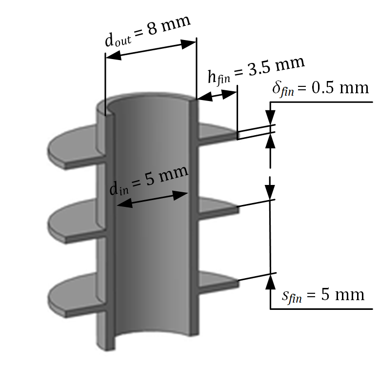
Figure 3 The real image (a) and the model (b) of a finned pipe of the coil of the dry unit
Uncertainty analysis was performed for each experiment according to the standard method (Coleman and Steele, 2009). For every measurement, uncertainty was obtained by calculating the standard deviation using the following formula:

Where  is the standard deviation; n is the number of repetitions; xi is the measurement value;
 is the arithmetic average of the measurements.
The standard uncertainty or standard deviation of the average for every set of measurements, accounting for random errors and time fluctuations in the measured values with a probability of 95% was determined using the following formula:

Where is the mean standard deviation; St is the Student coefficient.
The combined standard uncertainty for each test was determined by the following equation:

Where  is uncertainty due to errors in unmeasured systematic deviations of measured parameters, which can be calculated using the following formula:

Where f represents the uncertainty influence factor, which signifies how changes in a parameter depend on other measured values denotes the tolerance deviations of measuring sensors that characterize the accuracy of measurements.
For example, when determining the uncertainty  t in measuring the temperature of the hot process water at the inlet of the pipe coil, the influence of some factors should be taken into account. These factors were the temperature of the hot water tin,1 and chilled water at the outlet of the pipe coil tout,1, and the mass flow rate of water in the pipe coil Lm,1. Others include the velocity of the cooling air in the dry unit of the hybrid cooler
  and the air temperature at the inlet to the dry unit tin,2 with the corresponding accuracy of the sensors used, as presented in Table 1.
Table 1 Specification of the sensors used.
The average values with combined standard uncertainty of temperatures of the process water and cooling air at the inlet of the pipe coil and dry unit of the hybrid cooler are presented in Table 2 (for the plain pipes) and Table 3 (for the finned pipes). The mass flow of water in the pipe coil varied from 72.9 kg/h to 115.2 kg/h and the mass flow of the cooling air was between 76 kg/h and 320 kg/h, corresponding to the Reynolds numbers from 1.246·103 to 5.262·103.
Table 2 Average values with a combined standard uncertainty of temperature at the inlet of the plain pipe coil (tin,1) and temperature at the inlet of the dry unit of the hybrid cooler (tin,2) (experimental data)
The combined standard uncertainty calculations were performed for water mass flow rate measurements in the pipe coil of the dry unit. The results showed that the maximum combined standard uncertainty was 3.4044 kg/h, corresponding to an average value of 115.2 kg/h, leading to a maximum deviation of 3.01%. Therefore, the data analysis achieved an uncertainty of less than 5%.
2.2. Theoretical part
A mathematical model was developed to determine the thermal performance of the dry unit in the hybrid CCT. The input parameters of this model were the mass flow rate of process water, the temperature of the process water at the inlet to the pipe coil, the mass flow rate of cooling air, the air temperature at the inlet to the irrigation unit, and the geometrical dimensions of the plain and finned pipes.
In this study, the concept of capacitance rate is defined as the product of mass flow rate and heat capacity of the flow. The capacitance rate for hot process water C1, corresponding to liquid moving inside the pipe coil, can be expressed as
C1=Lm,1cp,1. (1)
The capacitance rate for cooling air flowing around the outer surface of the coil pipes is calculated using the following formula:
C2=Lm,2cp,2. (2)
The efficiency of the heat exchanger was generally determined by the ratio of the capacitance rates Cmin/Cmax, the NTU, and the flow arrangement. When considering heat transfer through the cylindrical wall and a constant value of the HTC, the following equation can be used to determine NTU.

where Cmin is the lower value of C1 and C2, calculated using Equations 1–2.
The linear HTC through the cylindrical wall of the pipe coil, considering the thermal resistance, can be formulated as:

where Rl is the thermal resistance to heat transfer through the cylindrical pipe wall,  is the thermal resistance to heat transfer from process water to the coil wall,
  is the resistance of thermal conductivity of the cylindrical pipe wall,
  is the thermal resistance to heat transfer from the pipe wall to spray water.
In the case of the plain pipes of the coil, Equation 3 can be transformed into

 1 is the convective HTC between the flow of process water within the pipes and the coil wall, 2 is the convective HTC between cooling air and the outer wall of the coil pipe,
  is the coefficient of thermal conductivity of the pipe material, din and dout are inner and outer diameters of the coil pipe, respectively.
Table 3 Average values with a combined standard uncertainty of temperature at the inlet of the finned pipe coil (tin,1) and temperature at the inlet of the dry unit of the hybrid cooler (tin,2) (experimental data)
In the case of the finned outer surface of the pipe coil, Equation 3 can be rewritten as

where  is the normalized HTC from cooling air to the outer wall of the coil pipe, and Fpl and Ffin are the areas of the plain and finned surface, respectively.
Table 4 presents Equation (4) for determining the HTC  for the longitudinal flow of straight pipes, based on the water flow regime within the pipe coil (Mikhailov et al. 2007).
Table 4 Calculating equations for

For a corridor arrangement of the pipes in the coil bundle (as in the experimental installation), the average HTC  for the cross-flow of cooling air was determined from Equation (5) presented in Table 5. S is the longitudinal pitch of the pipes, which is the distance between the axes of adjacent pipe rows along the airflow.
Table 5 Calculating equations for (Thulukkanam, 2024).
Where  is the correction coefficient.
The Reynolds number, referred to as the diameter of the outer pipe, can be calculated using the following Equation 6.

where fmin is the minimal open flow area of the air in the pipe bundle.
The average air temperature in the dry unit of the hybrid CCT has been identified as the determining temperature in Equations 5–6. The normalized HTC from cooling air to the outer wall of the circular finned pipe of the coil was calculated using Equation 7 (Madyshev et al., 2023; Kharkov et al., 2022).

where  is the correction coefficient, considering heat transfer in vertical sections of circular fins and horizontal sections of the pipe without finning, and it can be calculated using the following equation:

E is the fin efficiency coefficient,  is the correction factor for fin efficiency. The vertical surface area of the fins was calculated using the following equation:

the equation for the horizontal surface area of the fins and the sections between the fins is expressed as:

The fin efficiency coefficient can be determined from

where  is the hyperbolic tangent, b can be calculated using the following formula

The correction factor for fin efficiency, applicable for bhfin = 0.43–0.69 can be calculated using Equation (Yudin and Tokhtarova, 1974), which remains valid for bhfin within the range of 0.1 to 3.7:

Based on Equations 4–6, the overall HTC can be calculated for the plain pipes of the hybrid CCT coil. Additionally, Equations 7–8 should also be included for the finned pipes.
In general, the efficiency of heat transfer in heat exchangers was determined by the ratio of the actual energy exchanged to the maximum possible energy transfer (Liang et al., 2023):

In the case of series connections of pipes in the dry unit, the flow arrangement corresponds to multipass cross flow with counter connection for the passes. The number of pipes in the coil determines the number of passes. Therefore, the efficiency of the counter flow multipass dry unit of the hybrid CCT at different ratios of capacitance rates Cmin/Cmax can be defined using Equation 10, where  is the efficiency of a pass (a pipe) of the coil and Cmax is the highest value of C1 and C2.

and the efficiency of a pass is given by

Based on the calculated efficiency of the dry unit, the heat flow rate Q can be determined using Equation 9. The temperature of process water at the outlet of the pipe coil of the dry unit can be expressed as:

The mathematical model should incorporate additional parameters, including overall HTC kl, NTU (for single and multiple passes), and efficiency of a pass (a pipe) of the coil  . The output parameters of the model comprised the efficiency of multipass crossflow with counterflow connection of the passes
  heat flow rate Q, and water temperature at the outlet of the pipe coil tout,1.
To validate the mathematical model developed for the removal of heat from the surface of the plain and finned pipes in the hybrid CCT coil, experimental studies were conducted. The input parameters of the mathematical model correspond to the range of conditions used in the experiments. For the pipe coil examined, the surface area of the plain pipes was 0.0613 m2, while the area of the finned pipes was 0.227 m2.
The finning coefficient, defined as the ratio of the finned to the plain areas, was 3.01. The thermal conductivity coefficients of copper pipes and steel fin material were assumed to be 394 W/(m·K) and 17.5 W/(m·K), respectively.
Previous studies of the dry unit of the CCT showed that the share of heat transfer due to natural convection (the share of heat loss in the ambient) reached 25%, especially at low air velocities (Madyshev and Khar’kov, 2024). In this regard, when experimentally determining the heat flow rate, the influence of heat loss on the temperature of the water at the outlet of the pipe coil tout,1 should be considered. Therefore, the experimental values of the heat flow rate can be corrected using the following formula:

where Qloss is the heat loss, expressed as

Where lb is the total length of the return bends with outer diameter db, tw,b is the average temperature of the outer wall of the return bends, and t0 is the average ambient temperature.
The heat flow from hot water into the ambient during the fluid flow in the return bends of the dry unit in hybrid CCT can be determined by heat transfer at free convection. Since the return bends possess horizontal and vertical parts, the HTC  will be calculated as the average value. Therefore, with Gr·Pr from 103 to 108, the criterion equation describing the average heat transfer from the surface of horizontally curved pipes can be calculated using Equation 12, where
  is a coefficient considering the curvature of the return bends.

The criterion Equations (13) describing the average heat transfer from the vertically positioned curved return bends depending on the Gr·Pr value are presented in Table 6 (Madyshev et al., 2023).
Table 6 Calculating equations


The curvature of the return bend with radius r should be considered using the coefficient, given by

In Equations 12–13, the air properties were defined at the average ambient temperature. The coefficient of heat transfer from the outer surface of the return bend to the ambient  can be determined using the following formula:

The temperature of the process water at the outlet of the pipe coil, considering the correction of the experimental value of the heat flow rate Q', can be written as:

According to the determined values of HTC from the cooling air in the dry unit of the hybrid CCT, shown in Figure 4, the normalized HTC  for the pipes with fins is lower than that of plain pipes in the coil. This occurs because the addition of fins increases the heat transfer area, leading to a reduction in HTC. It was important to acknowledge that the value of the correction coefficient
  was less than 1. Across the entire range of Reynolds numbers analyzed, the decrease in did not exceed 12.7%.

Figure 4 HTC curves from cooling air for plain pipes (1) and finned pipes (2).
Figure 5 presents the change in the overall HTC, calculated using Equations 4–8, for the dry unit of the hybrid CCT under different types of coil pipes. Despite the slight decrease in the normalized HTC  from the air side (Figure 4), the circular finning with steel fins enhanced the coefficient kl by a factor ranging from 2.56 to 2.74 times, depending on the Reynolds number. This increase was attributed to the significant expansion of the heat transfer area, which was 3.7 times for finned pipes compared to plain pipes. Additionally, the maximum fin efficiency coefficient depends on the material used, with E = 0.997 for copper and E = 0.942 for carbon steel.

Figure 5 Overall HTC curves of the dry unit for plain pipes (1) and finned pipes (2).
The estimation results of the thermal resistance of the dry unit in the hybrid CCT, presented in Figure 6, show that the primary resistance was observed in the heat transfer from the cooling airflow (Rl, /Rl more than 92%). Therefore, changing the mass flow of water in the pipe coil Lm,1 had practically no influence on the value of the overall HTC. Based on observation, the circular finning of the pipe led to a slight decrease (on average by 2.3–4.2%) in the ratio of Rl,/Rl. with an increase in the mass flow rate of the air (and, respectively, the Reynolds number).

Figure 6 Ratio Rl,/Rl for plain (dashed lines) and finned pipes (solid lines) under changes in the mass flow rate of process water in the pipe coil Lm,1: (1) 72.9 kg/h; (2) 108.4 kg/h; (3) 95.1 kg/h; (4) 115.2 kg/h.
The incorporation of fins into the pipe coil of the dry unit greatly enhanced NTU and the efficiency of heat transfer. In the case of plain pipes, the maximum heat transfer efficiency  and NTU were 0.198 and 0.2266, respectively, as shown in Figure 7a. At the same time, for the case of finned pipes the = 0.462 and NTU = 0.652, representing 2.34 fold improvement in efficiency.
The highest values of NTU were observed at low mass flow rates of cooling air. This can be attributed to the increase in the Reynolds number for airflow, which elevates the maximum possible amount of heat transferred Qmax, leading to lowered efficiency . Additionally, increasing the mass flow rate in the pipe coil led to a slight improvement in the heat transfer efficiency. For example, when using plain pipes, an increase in Lm,1 by 48.5% corresponds to an average rise in  by 1.6%, while an increase in Lm,1 by 21.1% led to an average rise of 1.3% in (Figure 7).

Figure 7 Efficiency for plain pipes (dashed lines) and finned pipes (solid lines) of the dry unit against NTU under changes in the mass flow rate of process water in the pipe coil Lm,1: (1) 72.9 kg/h; (2) 108.4 kg/h; (3) 95.1 kg/h; (4) 115.2 kg/h.
Calculations based on the developed mathematical model showed that the fins on the coil pipes in the dry unit of the hybrid CCT significantly enhanced the heat flow rate Q. As presented in Figure 8, the Q values, influenced by the Reynolds number, increased by a factor of 2.63–3.22. This is due to a rise in the overall HTC on average by 2.64 times, as well as an increase in the temperature difference between the water entering the inlet to the pipe coil and the air at the inlet to the unit (by an average of 3.0 °C). As the Re2 value increases, there is a tendency for the heat flow rate to improve. Furthermore, the rise in the mass flow rate of the airflow by 2.7 times in the hybrid CCT, led to an increase in Q by 70% and 50% for plain and finned pipes.

Figure 8 Experimental (points) and calculated values (solid lines) of the heat flow rate of the dry unit for plain pipes (1) and finned pipes (2) under changes in the mass flow rate of process water in the pipe coil Lm,1: (3) 72.9 kg/h, (4) 108.4 kg/h, (5) 95.1 kg/h, (6) 115.2 kg/h.
The validation of calculated and experimental data on the estimation of the thermal performance of the designed CCT dry unit showed satisfactory convergence, as presented in Figure 8. The experimental value of the heat flow rate was determined by Equation 11, considering the additional water chilling in the return bends of the dry unit during natural convection. For plain pipes of the coil, the average deviation was 6.52% at water mass flow rate Lm,1 of 72.9 kg/h and 8.43% at Lm,1 = 108.4 kg/h. The maximum relative error in this case did not exceed 14.1%.
In the case of finned coil pipes, the experimentally obtained heat flow rates were generally lower than the calculated values. At Lm,1 = 95.1 kg/h, the maximum relative error was 12.8%, with an average error of 8.37%. The smallest deviation between the experimental and calculated values of the heat flow rate occured at Lm,1 = 115.2 kg/h, where the average error was 6.14%, and the maximum reached 10.4%.
The outlet water temperature from the pipe coil of the dry unit tout,1, considering the correction of the experimental value of the heat flow rate, was estimated using Equation 14. The value of tout,1 was influenced by the initial temperature of water at the inlet to the pipe coil, the mass flow rate, and the heat flow rate. As shown in Figure 9, tout,1 decreases with an increasing Reynolds number of the air in all examined cases. The highest value was observed in the coil with plain pipes, which is caused by the low efficiency of heat transfer. When using finned pipes, as presented in Figure 9, 2 curves are obtained at different mass flow rates of water in the coil. The variation arises from differing water temperatures at the coil inlet. For instance, the inlet water temperature was 0.6–0.8 °C at Lm,1 = 115.2 kg/h, which was higher at Lm,1 = 95.1 kg/h, as detailed in Table 3). This determined the presence of the temperature difference (no more than 1.1 °C) between 2 mass flow rates of water in the finned pipe coil.
A comparison of the calculated and experimental values of the water temperature at the outlet from the pipe coil of the dry unit of the hybrid CCT proves the adequacy of the developed mathematical model. For example, when using plain pipes, the maximum deviation between the experimental and calculated values of tout,1 is 0.39% with the mass flow rate of water in the coil Lm,1 of 72.9 kg/h, and 0.26% with Lm,1 = 108.4 kg/h. In the case of finned pipes, the maximum deviation of the calculated and experimentally obtained values of the water temperature is 0.82% at Lm,1 = 95.1 kg/h and 0.635% at Lm,1 = 115.2 6 kg/h (Figure 9).

Figure 9 Experimental (points) and calculated values (solid lines) of the water temperature at the outlet of the pipe coil for plain pipes (1) and finned pipes (2) under changes in the mass flow rate of process water in the pipe coil Lm,1: (3) 72.9 kg/h; (4) 108.4 kg/h; (5) 95.1 kg/h; (6) 115.2 kg/h.
The results on the distribution of thermal resistance of heat transfer, HTC, and efficiency of the developed design of the dry unit of the hybrid CCT with the finned pipe coil and the ICP were obtained. The application of the mathematical model makes it possible to evaluate the heat transfer efficiency at different mass flow rates of cooling air and process water. Furthermore, the model can be used to improve the heat flow rate by selecting the appropriate design characteristics of the pipe bundle, including the flow arrangement and fin dimensions.
Further studies of the hybrid CCT for chilling process water, operating in dry mode, are intended to determine the optimal ratio of gas and liquid phase rates to improve the thermal performance, as well as to evaluate the effect of the fin material of the coil pipes. The impact of the initial water and air temperatures on the thermal characteristics of the dry unit of the hybrid CCT was also planned.
In conclusion, this study developed a mathematical model to estimate the heat transfer efficiency of the dry unit in hybrid CCT. The results showed that the variation in the mass flow of water in the pipe coil from 72.9 kg/h to 115.2 kg/h did not influence the linear HTC in the unit operating in dry mode. This is because the primary thermal resistance of more than 92% occurred in heat transfer from cooling air. The finning of the pipes led to increased NTU and a rise in the heat transfer efficiency by 2.34 times. Furthermore, a finned coil of the dry unit of the CCT, which operated in dry mode, facilitated the rise in the heat flow rate by 2.63–3.22 times, depending on the Reynolds number for the cooling airflow. The proposed mathematical model of the water chilling in the pipe coil of the dry unit was in line with the results of the experimental determination of the heat flow rate (the maximum deviation is less than 14.1%) and the temperature of the water at the outlet of the coil (the maximum deviation is 0.82%).
The authors are grateful to the Russian Science Foundation, received in 2023, Project No. 23-79-01034), https://rscf.ru/project/23-79-01034/, for supporting the study.
Author Contributions
I. Madyshev: Conceptualization, Funding acquisition, Investigation, Methodology, Project administration, Writing – original draft. V. Kharkov: Data curation, Investigation, Resources, Supervision, Writing – review & editing. M. Vakhitov: Software, Visualization. M. Kuznetsov: Formal analysis, Validation.
Conflict of Interest
The authors declare no conflicts of interest.
List of abbreviations and symbols
C = capacitance rate, W/K
cp = heat capacity, J/(kg·K)
CT = cooling tower
d = diameter of the coil pipe, m
F = surface area, m2
Gm = mass flow rate of gas (air), kg/s
Gr = Grashof number, unitless
h = height, m
HTC = heat transfer coefficient
ICP = inclined-corrugated plates
k = overall HTC, W/
l = total length of the coil pipes, m
Lm = mass flow rate of liquid (water), kg/s
NTU = heat transfer units, pcs.
Nu = Nusselt number, unitless
Pr = Prandtl number, unitless
Q = heat flow rate, W
R = thermal resistance, /W
Re = Reynolds number, unitless
s = spacing, m
t = temperature, K
z = number of passes, pcs.
Greek Symbols

Subscripts
* = normalized value
1 = process water
2 = cooling air
b = return bend
f = film
fin = fin/finning
in = inlet, inner
l = linear
max = maximum
min = minimum
out = outlet, outer
pl = plain
w = wall
Al-Waked, R & Behnia, M 2007, ‘Enhancing performance of wet cooling towers’, Energy Conversion and Management, vol. 48, no. 10, pp. 2638–2648, https://doi.org/10.1016/j.enconman.2007.04.018
Arefimanesh, A & Heyhat, MM 2024, ‘Investigation of the simultaneous effect of fouling and ambient conditions on cooling performance and water consumption of a wet cooling tower’,Case Studies in Thermal Engineering, vol. 58, article 104426, https://doi.org/10.1016/j.csite.2024.104426
Bahadori, A 2016, ‘Cooling tower and cooling water circuits’, Essentials of Oil and Gas Utilities, Elsevier, pp. 159-192, https://doi.org/10.1016/B978-0-12-803088-2.00005-5
Berawi, MA 2014. ‘Editorial Notes: Integrating Engineering Design and Technology Towards Sustainable Developmen’, International Journal of Technology, vol. 1, no. 1, p. 2–3. https://doi.org/10.14716/ijtech.v1i1.41
Budihardjo, Nasruddin & Nugraha, MH 2015, ‘Experimental and simulation study on the performance of counter flow closed cooling tower systems’, International Journal of Technology, vol. 6, no. 3, pp. 365-379, https://doi.org/10.14716/ijtech.v6i3.986
Coleman, HW & Steele, WG 2009, ‘Experimentation, validation, and uncertainty analysis for Engineers’, John Wiley & Sons. https://doi.org/10.1002/9780470485682
Gao, M, Zhang, L, Wang, NN & Shi, YT 2016, ‘Influence of non-uniform layout fillings on thermal performance for wet cooling tower’. Applied Thermal Engineering, vol. 93, pp. 549-555. https://doi.org/10.1016/j.applthermaleng.2015.09.054
Hassab, MA, Khamis, MM, Sadek, LA & Qassem, MA 2023, ‘Thermal and experimental analysis of cross-flow closed cooling tower’, Alexandria Engineering Journal, vol. 69, pp. 739-746, https://doi.org/10.1016/J.AEJ.2023.02.012
He, S, Gurgenci, H, Guan, Z, Hooman, K, Zou, Z & Sun, F 2016, Comparative Study on the Performance of Natural Draft Dry, Pre-Cooled and Wet Cooling Towers. Applied Thermal Engineering, vol. 99, pp. 103-113, https://doi.org/10.1016/j.applthermaleng.2016.01.060
Heyns, JA & Kröger, DG 2010, ‘Experimental investigation into the thermal-flow performance characteristics of an evaporative cooler’, Applied Thermal Engineering, vol. 30, no. 5, pp. 492–498, https://doi.org/10.1016/j.applthermaleng.2009.10.010
Howongsakun, T, Theerakulpisut, S, Sujumnongtokul, P & Palasan, P 2016, ’The behavior of lewis number in finned tube cooling coils under highly moist inlet air conditions’, International Journal of Technology, vol. 7, no. 7, pp. 1253-1259, https://doi.org/10.14716/ijtech.v7i7.4654
Jiang, J-J, Liu, X-H & Jiang, Y 2013, ‘Experimental and numerical analysis of a cross-flow closed wet cooling tower’, Applied Thermal Engineering, vol. 61, no. 2, pp. 678-689, https://doi.org/10.1016/j.applthermaleng.2013.08.043
Kharkov, VV, 2018, ‘Mathematical modelling of thermolabile solutions concentration in vortex chamber’, Journal of Physics: Conference Series, vol. 980, no. 1, p. 012006, https://doi.org/10.1088/1742-6596/980/1/012006
Kharkov, VV, Madyshev, IN, Kuznetsov, MG, Galimova, AT & Sagdeev, AA 2022, ‘Experimental study of pressure loss in hybrid cooling tower with finned tube radiator’, Journal of Physics: Conference Series, vol. 2373, no. 2, article 022055, https://doi.org/10.1088/1742-6596/2373/2/022055
Liang, D, Yang, K, Gu, H, Chen, W & Chyu, MK 2023, ‘The effect of unit size on the flow and heat transfer performance of the “Schwartz-D” heat exchanger’, International Journal of Heat and Mass Transfer, vol. 214, article 124367, https://doi.org/10.1016/j.ijheatmasstransfer.2023.124367
Liang, J, Tian, Y, Yang, S, Wang, Y, Yin, R & Wang, Y 2024, ‘Long-term operation optimization of circulating cooling water systems under fouling conditions’, Chinese Journal of Chemical Engineering, vol. 65, pp. 255–267, https://doi.org/10.1016/j.cjche.2023.08.008
Madyshev, I, Kharkov, V & Dmitriev, A, 2020. ‘Cooling efficiency of filler unit in non-chemical cooling tower with advanced contact surface’. E3S Web of Conferences, vol. 193, article 01044. https://doi.org/10.1051/e3sconf/202019301044
Madyshev, I, Kharkov, V, Mayasova, A & Kurbangaliev, R 2023, ‘Cooling efficiency of hybrid cooling tower with finned tube radiator’, E3S Web of Conference, vol. 458, article 01003, https://doi.org/10.1051/e3sconf/202345801003
Madyshev, IN & Khar’kov, VV 2024, ‘Determination of heat and mass emission coefficients in a hybrid cooling tower with transversely finned radiator pipes’, Journal of Engineering Physics and Thermophysics, vol. 97, pp. 1050-1057. https://doi.org/10.1007/s10891-024-02976-1
Madyshev, IN & Kharkov, VV 2024, ‘Thermal study of hybrid-type cooling tower with finned tube’, Thermal Science and Engineering Progress, vol. 56, article 103023, https://doi.org/10.1016/j.tsep.2024.103023
Madyshev, IN, Kharkov, VV, Dmitrieva, OS & Zinurov, VE 2022, ‘Energy saving in distillation by combining vortex contact device and thermal effects’, Thermal Science and Engineering Progress, vol. 34, aticle 101431, https://doi.org/10.1016/j.tsep.2022.101431
Mikhailov, GM, Mikhailov, VG, Kondakova, LA & Reva, LS 2007. ‘Determination of the coefficient of convective heat transfer in a transient pipe flow at high grashof numbers’, Theoretical Foundations of Chemical Engineering, vol. 41, no. 4, pp. 414–416, https://doi.org/10.1134/S0040579507040124
Muthukumar, P, Naik, BK, & Goswami, A 2019, ‘Performance evaluation of a mechanical draft cross flow cooling towers employed in a subtropical region’, Journal of The Institution of Engineers (India): Series C, vol. 100, pp. 333–341, https://doi.org/10.1007/s40032-018-0441-y
Nemati, H, Ardekani, MM, Mahootchi, J & Meyer, JP 2024, ’Cooling Tower’, In: Fundamentals of Industrial Heat Exchangers, Elsevier, pp. 75–88. https://doi.org/10.1016/B978-0-443-13902-4.00034-2
Rahem, T, Aissati, A & Sidi Ali, K 2018, ’Comparative study between three types of cooling towers: dry, wet and hybrid’, In: Conference: 12ème Congrès National de la Physique et de ses Applications, Algiers, Algeria
Rasheed, NS & Makki, HF 2023, ’Thermal performance of hybrid (dry/wet) cooling tower with in modified approach’, AIP Conference Proceedings, vol. 2806, article 030009, https://doi.org/10.1063/5.0163038
Ravelo-Mendivelso, KY, Villate-Fonseca, MT, Hernández-Vásquez, JD, Miranda-Samper, OM, Pacheco-Torres, PJ & Campuzano, MJ 2023, ‘Thermal and hydrodynamic performance analysis of a shell and tube heat exchanger using the AHP multicriteria method’, International Journal of Technology, vol. 14, no. 3, pp. 522–535, https://doi.org/10.14716/ijtech.v14i3.6000
Reuter, H & Anderson, N 2016, ‘Performance evaluation of a bare tube air-cooled heat exchanger bundle in wet and dry mode’, Applied Thermal Engineering, vol. 105, pp. 1030-1040, https://doi.org/10.1016/j.applthermaleng.2016.06.008
Sati, V & Periaswamy, S 2024, ‘Numerical simulation and experimental investigation on phase change materials based energy storage system for cooling the water in process industries towards water conservation and environmental sustainability’. Journal of Energy Storage, vol. 85, article 110997, https://doi.org/ 10.1016/j.est.2024.110997
Sonia, P, Hossein, S, Amirmohammad, S, Mohammad, N & Fatemeh, EH 2016, ‘Thermo-economic study of hybrid cooling tower systems. International Journal of Physical Sciences, vol. 11, no. 22, pp. 306–320, https://doi.org/10.5897/IJPS2016.4565
Sun, Y, Guan, Z & Hooman, K 2017, ‘A review on the performance evaluation of natural draft dry cooling towers and possible improvements via inlet air spray cooling’, Renewable and Sustainable Energy Reviews, vol. 79, pp. 618-637, https://doi.org/10.1016/j.rser.2017.05.151
Susmiati, Y, Purwantana, B, Bintoro, N & Rahayoe, S 2022, ’Heat transfer characteristics in vertical tubular baffle internal reboiler through dimensional analysis’, International Journal of Technology, vol. 13, no. 3, pp. 508-517, https://doi.org/10.14716/ijtech.v13i3.5170
Taimoor, AA, Saeed, U, Rather, S, Al-Shahrani, S, Bamufleh, HS, Alhumade, H, Sulaimon, AA, Alalayah, WM & Shariff, AM 2022, ‘Economic and technical analysis of a hybrid dry cooling cycle to replace conventional wet cooling towers for high process cooling loads, Energies, vol. 15, no. 21, article 7986, https://doi.org/10.3390/en15217986
Thulukkanam, K 2024, Heat exchanger design handbook, CRC Press, New York. https://doi.org/10.1201/b14877
Vitkovic, P, Storch, V, Puncochar, J, Stodulka, J, 2016. Measurement of Thermal Performance of Hybrid Cooling Tower. AIP Conference Proceedings, Volume 1768, p. 020023. https://doi.org/10.1063/1.4963045
Wei, X, Li, N, Peng, J, Cheng, J, Hu, J & Wang, M 2017, ‘Performance analyses of counter-flow closed wet cooling towers based on a simplified calculation method’, Energies, vol. 10, no. 3, article 282, https://doi.org/10.3390/en10030282
Whulanza, Y, Kusrini, E, Suwartha, N & Maknun, I.J 2024., ’Addressing water sustainability in the 21st century: the role of engineering and technology’, International Journal of Technology, vol. 15, no. 3, pp. 472–480, https://doi.org/10.14716/ijtech.v15i3.7088
Yu, JH, Qu, ZG & Zhang, JF 2023, ‘Air flow distribution prediction and parametric sensitivity analysis of horizontal-arrangement parallel-path hybrid cooling towers’, Energy and Buildings, vol. 295, article 113266, https://doi.org/10.1016/j.enbuild.2023.113266
Yudin, VF & Tokhtarova, LS 1974, ’Convective heat transfer in transverse flow around bundles of finned tubes’, Energomashinostroyeniye, vol. 1, pp. 19-21
Zaza, A, Bennouna, EG, Iranzo, A, El Hammami, Y & Pino, FJ 2024, ‘Optimizing sustainability in hybrid cooling towers: investigating fouling resistance, water quality correlations, modeling, and cleaning strategies for thermal power plants’, Journal of Cleaner Production, vol. 462, article 142706, https://doi.org/10.1016/j.jclepro.2024.142706
Zhao, C, Wang, M, Gao, Q, Cheng, S, He, S, Zhao, J, Zhan, J, Liu, Z, Geng, Z, Zhang, S, Qi, J, Gao, M & Shi, Y 2023, ‘Investigation on the cooling performance of mechanical draft dry-wet hybrid cooling tower’, Applied Thermal Engineering, vol. 228, article 120473. https://doi.org/10.1016/j.applthermaleng.2023.120473
Zhou, Y, Zhu, X & Ding, X 2018, ‘Theoretical investigation on thermal performance of new structure closed wet cooling tower’, Heat Transfer Engineering, vol. 39, no. 5, pp. 460–472, https://doi.org/10.1080/01457632.2017.1312899